Their are lots of advantages to making 3d graphics compared to 2d graphics, however their are limitations to making 3d graphics which might not occur in 2d. For example, when creating 3d graphics yuo have to consider your poly count? Your poly count is the amount of poly’s being rendered per frame, you render your 3d graphics in a wire frame state first rather than shaded becasue it is much quicker. The poly’s are what make up the 3d object and the more complex and detailed the object the higher the poly count will be. File size Another problem with having a high poly count is that the file size will be very high, an this general means you will need a high quality CPU (Central processing unit) to render your work. The better the CPU the more poly’s it can handle and render at once so this gives you quicker work pace but this type of high end equipment has a high end price tag and is expensive so not everyone can afford this type of equipment. http://bigcostas.wordpress.com/limitations-of-3d-poly-count-file-size-and-rendering-times/ Real-time rendering Real-time rendering is one of the interactive areas of computer graphics, it means creating synthetic images fast enough on the computer so that the viewer can interact with a virtual environment. The most common place to find real-time rendering is in video games. The rate at which images are displayed is measured in frames per second (frame/s) or Hertz (Hz). The frame rate is the measurement of how quickly an imaging device produces unique consecutive images. If an application is displaying 15 frame/s it is considered real-time http://en.wikipedia.org/wiki/Real_Time_rendering
Autodesk 3ds Max, formerly 3D Studio Max, is 3D computer graphics software for making 3D animations, models, and images. It was developed and produced by Autodesk Media and Entertainment. It has modeling capabilities, a flexible plugin architecture and can be used on the Microsoft Windows platform. It is frequently used by video game developers, TV commercial studios and architectural visualization studios. It is also used for movie effects and movie pre-visualization. In addition to its modeling and animation tools, the latest version of 3ds Max also features shaders (such as ambient occlusion and subsurface scattering), dynamic simulation, particle systems, radiosity, normal map creation and rendering, global illumination, a customizable user interface, and its own scripting language. http://en.wikipedia.org/wiki/3D_Studio_Max
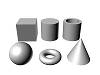
Geometry: Represented by an image of a sphere, selecting this subset lets you draw any three-dimensional geometry. The default is Standard Primitives (box, sphere, etc), but using the dropdown menu you can select Extended Primitives, Compound Objects, Particle Systems, Patch Grids, NURBS Surface, and Dynamic Objects.
Shapes: Represented by a shapes icon, this subset gives access to the drawing tools for flat, 2D objects: Splines (circles, rectangles, etc.) and NURBS curves..
Lights: Subset represented by a “flashlight” with the tools to create light sets: Target Spot, Free Spot, Target Direct, Free Direct, and Omni. The dropdown menu for this subset contains only Standard types.
Cameras: Represented by a graphic of a camera, this contains the camera types: Target and Free. The dropdown menu for this subset contains only Standard types.
Helpers: The icon for this subset looks like a small tape measure, and like a tape measure the tools contained within are useful to the construction of your scene. The dropdown options for this subset are Standard (dummy, tape measure, compass, etc.), Atmospheric Apparatus, Camera Match, and Manipulators. You may see other options here if you have certain plugins (like Reactor or Shag Hair).
Space Warps: This subset (represented by an icon depicting several waves) lets you create forces and other environmental factors in your scene. The dropdown options include Forces (motor, push, vortex, etc.), Deflectors, Geometric/Deformable, and Modifier-Based. Like the above, you may see other options if you have additional plugins.
Systems: This subset, whose icon depicts two gears, lets you create complex systems with the push of a few buttons: bones, sunlight systems, full biped systems, and ring arrays. The dropdown menu for this subset contains only Standard types.
The last in the four panels displayed above is merely an example of the selection dropdown menus on the various subsets. This one displays the options available on the Geometry subset.
Pivot: Adjust the pivot points of objects, including how the move/rotate/scale tools affect them (such as setting them to affect only the pivot points affect the object only, or affect the entire hierarchy), which will change the results of using those tools; you can also set the alignment in relation to each other and the “world”, or change whether or not changes made to a “parent” object affect that object’s linked “children”. This is key to “forward kinematics” (a method of animation where you move things in a straightforward fashion, one pivot-point at a time).
IK: Here you can control your IK (inverse kinematics) settings. IK is an animation method that can control the behavior of an entire chain of objects at once, as though they truly were attached and affected by each others’ forces (for example: if you pull on a human wrist, the wrist alone will not move; it will pull the forearm with it, which will in turn draw the upper arm, then shoulder, then body behind). We’ll talk about this in more detail in a separate lesson on IK.
Link Info: This subset is very simple; it lets you either lock or unlock movement, rotation, or scaling on an axis, and determine on which axes motion, rotation, or scaling is inherited.
Parameters: Here you can assign a controller to your motion (such as position, rotation, or scale), create keys for those controllers, or edit your key frame information to set motion to ease into a key, ease out of a key, or various other settings.
Trajectories: This lets you view the path an object travels over time, and use that visual to control the path.
LightWave is a software package used for rendering 3D images, both animated and static. It includes a rendering engine that supports such advanced features as realistic reflection and refraction, radiosity, and caustics. The 3D modeling component supports both polygon modeling and subdivision surfaces. The animation component has features such as reverse and forward kinematics for character animation, particle systems and dynamics. Programmers can expand LightWave's capabilities using an included SDK which offers LScript scripting (a proprietary scripting language) and common C language interfaces. http://en.wikipedia.org/wiki/LightWave_3D
Autodesk Maya, commonly shortened to Maya, is 3D computer graphics software that runs on Windows, Mac OS and Linux, originally developed by Alias Systems Corporation (formerly Alias|Wavefront) and currently owned and developed by Autodesk, Inc. It is used to create interactive 3D applications, including video games, animated film, TV series, or visual effects. The product is named after the Sanskrit word Maya, the Hindu concept of illusion.
Cinema 4D is a 3D modeling, animation and rendering application developed by MAXON Computer GmbH of Friedrichsdorf, Germany. It is capable of procedural and polygonal/subd modeling, animating, lighting, texturing, rendering, and common features found in 3d modelling applications.
SketchUp (also known as Trimble SketchUp) is a 3D modeling program for a broad range of applications such as architectural, civil, mechanical, film as well as video game design — and available in free as well as 'professional' versions. The program highlights its ease of use, and an online repository of model assemblies (e.g., windows, doors, automobiles, entourage, etc.) known as 3D Warehouse enables designers to locate, download, use and contribute free models. The program includes a drawing layout functionality, allows surface rendering in variable "styles," accommodates third-party "plug-in" programs enabling other capabilities (e.g., near photo realistic rendering) and enables placement of its models within Google Earth. In April 2012, Google, the previous owner of SketchUp, announced it would sell the program to Trimble, a company best known for GPS location services.
ZBrush is a digital sculpting tool that combines 3D/2.5D modeling, texturing and painting. It uses a proprietary "pixol" technology (see below) which stores lighting, color, material, and depth information for all objects on the screen. The main difference between ZBrush and more traditional modeling packages is that it is more akin to sculpting. ZBrush is used as a digital sculpting tool to create high-resolution models (up to ten million polygons) for use in movies, games, and animations. It is used by companies ranging from ILM to Electronic Arts. ZBrush uses dynamic levels of resolution to allow sculptors to make global or local changes to their models. ZBrush is most known for being able to sculpt medium to high frequency details that were traditionally painted in bump maps. The resulting mesh details can then be exported as normal maps to be used on a low poly version of that same model. They can also be exported as a displacement map, although in that case the lower poly version generally requires more resolution. Or, once completed, the 3D model can be projected to the background, becoming a 2.5D image (upon which further effects can be applied). Work can then begin on another 3D model which can be used in the same scene. This feature lets users work with extremely complicated scenes without heavy processor overhead. ZBrush was created by the company Pixologic Inc, founded by Ofer Alon (also known by the alias "Pixolator") and Jack Rimokh. The software was presented in 1999 at SIGGRAPH. The demo version 1.55 was released in 2002, and the version 3.1 was released in 2007. ZBrush 4 for Windows and Mac systems was announced on April 21, 2009 for an August release, but was later postponed. Version 3.5 was made available in September the same year, and includes some of the newer features initially intended for ZBrush 4. Through GoZ ("Go ZBrush"), available in Version 4, ZBrush offers integration with Autodesk Maya, Autodesk 3ds Max, Cinema4D NewTek's LightWave3D and Modo.
Box modelling is a technique in 3D modelling where you take a basic primitive shape (like a box, cylinder or others) and make the basic shape “rough draft” of your final model from there you sculpt out your final model. The process uses various tools and steps that sometimes get repeated again and again until you're done. Despite the fact you’re repeating these steps you will model faster and control the amount of detail you wish to add, slowly building your model up from ground level of detail to high level. http://en.wikipedia.org/wiki/Box_modelling Extrusion Modelling Although it is necessary to keep in mind how the geometry will develop, extrusion modelling allows for a lot of freedom in where you place vertices at the beginning of the modelling process. In this example, it enables you to trace the outline of a photograph closely. http://my.safaribooksonline.com/book/animation-and-3d/9780470102602/working-with-meshes/extrusion_modeling_and_box_modeling Primitive Modelling Primitives are the building blocks of 3D-basic geometric forms that you can use as is or modify with transforms and Booleans. Although it's possible to create most of these objects by lathing or extruding 2D shapes, most software packages build them in for speed and convenience. Common 3D Primitives: Cube, Cylinder, Tube, Sphere, Torus, Cone
Specialised Modelling In 3D computer graphics, polygonal modeling is an approach for modeling objects by representing or approximating their surfaces using polygons. Polygonal modeling is well suited to scanline rendering and is therefore the method of choice for real-time computer graphics. Alternate methods of representing 3D objects include NURBS surfaces, subdivision surfaces, and equation-based representations used in ray tracers. See polygon mesh for a description of how polygonal models are represented and stored. http://en.wikipedia.org/wiki/Polygonal_modeling
Many modeling programs do not strictly enforce geometric theory; for example, it is possible for two vertices to have two distinct edges connecting them, occupying exactly the same spatial location. It is also possible for two vertices to exist at the same spatial coordinates, or two faces to exist at the same location. Situations such as these are usually not desired and many packages support an auto-cleanup function. If auto-cleanup is not present, however, they must be deleted manually.
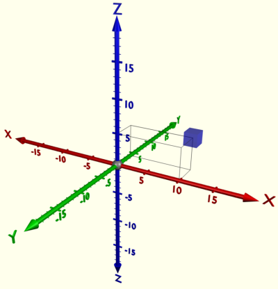
The 3D co-ordinates are pretty much the same as 2D co-ordinates except there’s a third axis known as the Z or ‘depth’ axis. 3D programs operate on a grid of 3D co-ordinates.
Geometric Theory and Polygons
The basic object used in mesh modeling is a vertex, a point in three dimensional space. Two vertices connected by a straight line become an edge. Three vertices, connected to each other by three edges, define a triangle, which is the simplest polygon in Euclidean space. More complex polygons can be created out of multiple triangles, or as a single object with more than 3 vertices. Four sided polygons (generally referred to as quads) and triangles are the most common shapes used in polygonal modeling. A group of polygons, connected to each other by shared vertices, is generally referred to as an element. Each of the polygons making up an element is called a face.
In Euclidean geometry, any three non-collinear points determine a plane. For this reason, triangles always inhabit a single plane. This is not necessarily true of more complex polygons, however. The flat nature of triangles makes it simple to determine their surface normal, a three-dimensional vector perpendicular to the triangle's surface. Surface normals are useful for determining light transport in ray tracing, and are a key component of the popular Phong shading model. Some rendering systems use vertex normals instead of face normals to create a better-looking lighting system at the cost of more processing. Note that every triangle has two face normals, which are on the same line but opposite from each other. In many systems only one of these normals is considered valid – the other side of the polygon is referred to as a backface, and can be made visible or invisible depending on the programmer’s desires.
A group of polygons which are connected by shared vertices is referred to as a mesh. In order for a mesh to appear attractive when rendered, it is desirable that it be non-self-intersecting, meaning that no edge passes through a polygon. Another way of looking at this is that the mesh cannot pierce itself. It is also desirable that the mesh not contain any errors such as doubled vertices, edges, or faces. For some purposes it is important that the mesh be a manifold – that is, that it does not contain holes or singularities (locations where two distinct sections of the mesh are connected by a single vertex).
Another common method of creating a polygonal mesh is by connecting together various primitives, which are predefined polygonal meshes created by the modeling environment. Common primitives include:
Cubes
Pyramids
Cylinders
2D primitives, such as squares, triangles, and disks
Specialized or esoteric primitives, such as the Utah Teapot or Suzanne, Blender's monkey mascot.
Spheres - Spheres are commonly represented in one of two ways:
Icospheres are icosahedrons which possess a sufficient number of triangles to resemble a sphere.
UV Spheres are composed of quads, and resemble the grid seen on some globes - quads are larger near the "equator" of the sphere and smaller near the "poles," eventually terminating in a single vertex.
In mathematics, specifically, in topology, a surface is a two-dimensional, topological manifold. The most familiar examples are those that arise as the boundaries of solid objects in ordinary three-dimensional Euclidean space - for example, the surface of a ball. On the other hand, there are surfaces, such as the Klein bottle, that cannot be embedded in three-dimensional Euclidean space without introducing singularities or self-intersections. To say that a surface is "two-dimensional" means that, about each point, there is a coordinate patch on which a two-dimensional coordinate system is defined. For example, the surface of the Earth is a two-dimensional sphere, and latitude and longitude provide two-dimensional coordinates on it. The concept of surface finds application in physics, engineering, computer graphics, and many other disciplines, primarily in representing the surfaces of physical objects. For example, in analyzing the aerodynamic properties of an airplane, the central consideration is the flow of air along its surface.
API, an abbreviation of application program interface, is a set of routines, protocols, and tools for building software applications. A good API makes it easier to develop a program by providing all the building blocks. A programmer then puts the blocks together. Most operating environments, such as MS-Windows, provide an API so that programmers can write applications consistent with the operating environment. Although APIs are designed for programmers, they are ultimately good for users because they guarantee that all programs using a common API will have similar interfaces. This makes it easier for users to learn new programs. http://www.webopedia.com/TERM/A/API.html Graphics pipline In 3D computer graphics, the terms graphics pipeline or rendering pipeline most commonly refers to the current state of the art method of rasterization-based rendering as supported by commodity graphics hardware. The graphics pipeline typically accepts some representation of a three-dimensional primitive as input and results in a 2D raster image as output. OpenGL and Direct3D are two notable 3d graphic standards, both describing very similar graphic pipelines. Per-vertex lighting and shading Geometry in the complete 3D scene is lit according to the defined locations of light sources, reflectance, and other surface properties. Some (mostly older) hardware implementations of the graphics pipeline compute lighting only at the vertices of the polygons being rendered; the lighting values between vertices are then interpolated during rasterization. Per-fragment or per-pixel lighting, as well as other effects, can be done on modern graphics hardware as a post-rasterization process by means of a shader program. Modern graphics hardware also supports per-vertex shading through the use of vertex shaders.
Clipping Geometric primitives that now fall completely outside of the viewing frustum will not be visible and are discarded at this stage.
Projection transformationIn the case of a Perspective projection, objects which are distant from the camera are made smaller. This is achieved by dividing the X and Y coordinates of each vertex of each primitive by its Z coordinate(which represents its distance from the camera). In an orthographic projection, objects retain their original size regardless of distance from the camera.
Viewport transformation The post-clip vertices are transformed once again to be in window space. In practice, this transform is very simple: applying a scale (multiplying by the width of the window) and a bias (adding to the offset from the screen origin). At this point, the vertices have coordinates which directly relate to pixels in a raster.
Scan conversion or rasterization Rasterization is the process by which the 2D image space representation of the scene is converted into raster format and the correct resulting pixel values are determined. From now on, operations will be carried out on each single pixel. This stage is rather complex, involving multiple steps often referred as a group under the name of pixel pipeline. Texturing, fragment shading At this stage of the pipeline individual fragments (or pre-pixels) are assigned a color based on values interpolated from the vertices during rasterization, from a texture in memory, or from a shader program.
The very first console release to support stereoscopic 3D was 3-D WorldRunner, released on the Famicom in Japan in 1987 and later for the NES in North America and Europe.
The game is a shooter that uses a ''behind the character'' perspective. 3D mode was optional and contingent on the player wearing a set of anaglyph red/green glasses to produce the 3D effect. Since the glasses supplied were made from flimsy cardboard, very few complete examples of the game are known to be in circulation.
More people where starting to get interested in 3D being used in games making designers focus there atention from 2D to 3D. An example of these games are Mario 64 or banjo and kazooie.
Mario 64
Banjo kazooie
There are lots of genres of games that have been in 3D it became very popular for gamers and designers. People would start playing shooting, adventure and puzzle games in 3D.
Aone in the Dark (1992)
Current Trends
Most 3D games today are more advanced and are now hyper-realistic, because of the success of the technology used in the industry Some games have been created which have the same qualities used in films, an example of games with these elements are:
Mass effect Series
Dead Rising frencise
3D in Animations
Technology has come a long way since the time of black and white television sets, especially in the field in of animation. Animation has evolved from very simple drawings to the basic 2D movies such as The Lion King and Little Mermaid. The next stage of animation’s evolution is a new, realistic, and exciting form of animation called 3D animation. An application known as computer graphic imagery or CGI has become an immense influence on the way 3D animation is produced today. CGI applies the concepts of 3D computer graphics to special effects. This application is used widely for visual effects because it allows not for only cheaper product, but also for a more realistic and higher quality product which is easier to control than the older methods of creating miniatures, drawings, or hiring extras. Without the use of CGI, many images would not be able to be produced using other technologies, and production would have to include expensive sets, actors, and props ("Computer-generated imagery").
Meet Buck is an animation made in 2010 by Denis Bouyer, Yann de Preval, Vincent E Sousa, Laurent Monneron and the sound design/mix was made by Julien Begault and the music is by Yannis Dumoutiers and Mickaël Védrine.
3D in Film and TV
Adventure Time (TV program)
"A Glitch Is a Glitch" is the fifteenth episode of the fifth season of the American animated television series Adventure Time. It was written, directed, and animated by David OReilly. It originally aired on Cartoon Network on April Fools Day.
Doctor Who (TV program)
Milk's founders are Nick Drew (Managing Director and Executive Producer), with Visual Effects Supervisors Jean-Claude Deguara and Nico Hernandez (also joint Heads of 3D), Sara Bennett (also Head of 2D), and Murray Barber, with Executive Producer and overall CEO of the company being a name and face familiar to fans through Doctor Who Confidential, Will Cohen.
Guy Ritchie’s Sherlock Holmes recently received the Outstanding Supporting Visual Effects in a Feature Motion Picture prize at the 8th annual VES Awards. Vfx supervisor Chas Jarrett led the effort behind more than 1000 effect shots to recreate Victorian London in 1891. In this article, we focus on three visual effects sequences from the film: the shipyard fight and the wharf explosion shot, both by Framestore, and the Tower Bridge shots by DNeg. http://www.fxguide.com/featured/Sherlock_Holmes/
Richardson, who has worked on every "Harry Potter" film, says technological advances like faster computer processors make some effects possible that could not have been attempted during the first or second "Harry Potter" movies, and he offers the Hall of Prophecies battle as an example. "Visual Effects can do better things, more realistic things. We had CG characters since the beginning, but the bar has been raised since then. I think the broomstick flying is better now than in the first film," says Richardson. http://entertainment.howstuffworks.com/harry-potter-phoenix2.htm
3D in Edutation
Torque 3D takes the world of advanced video game design and puts it in the power of your hands. Without any programming knowledge a Torque 3D user can quickly design detailed 3D game worlds with dynamic lighting, stunning water features and your choice of terrains. Physics for cloth dynamics, destructible objects, joints, and fluid buoyancy are built into the engine.
3D in Architecture Architect 3D brings the world of 3D design within everyone's reach! The software allows you to easily draw up plans of your home and design its structure, from the foundations to the roof.
From frames to masonry, electricity, heating, plumbing, and more. Design and view every detail of your project.You don't need to be an architect or building professional: Architect 3D provides you with all the tools and guidance you need to design your own project.
Design the bare-bones structure of your home
Effective wizards guide you through each step to create the bare-bones structure of your home: foundations, walls, framing, roofing, etc. Create an unlimited number of buildings, rooms, floors, mezzanines or split-levels to suit your project and your wishes!
Draw up detailed technical plans
Create a 2D plan of your house and add all the technical details for your project: electrical network, plumbing installations (from standard toilets to a whirlpool bathtub), heating, ventilation, air conditioning, etc.
Choose and plan your woodwork
Design and position your doors and windows according to your specifications: size, colour, texture, location, opening direction, etc. Add, remove, adjust and resize your woodwork components as often as you like!
Customise your materials
Select and compare different textures and materials: stone, brick, tiles, etc. Import a digital image of your chosen material, select existing materials from the library or create new ones from scratch.


_%5B!%5D_001.png)


+%5B!%5D_001.png)